Explore a custom ultra-slim aluminum wall shelving system with walnut-finish cabinets, stone panels, concealed support and integrated LED lighting.
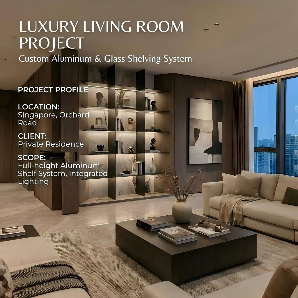
This wall-integrated display system combines ultra-slim aluminum shelf lines, warm walnut-finish cabinetry, marble-look or stone back panels and concealed linear lighting. The project is designed as a complete architectural wall composition for books, art objects, home-bar items and decorative collections rather than as a conventional box cabinet.
The aluminum shelves, wall substrate, back panels, base cabinets, lighting and electrical access must be coordinated together. The visual simplicity depends on careful preparation behind the finished surfaces.
The project relies on very thin horizontal lines. If the shelf structure, wall reinforcement or electrical route is not planned correctly, the finished wall can suffer from visible brackets, uneven alignment, excessive deflection or exposed wiring.
The solution should begin with the intended shelf span and displayed objects. Shelf depth, support location, wall construction and weight expectations must be checked before selecting the final aluminum section.
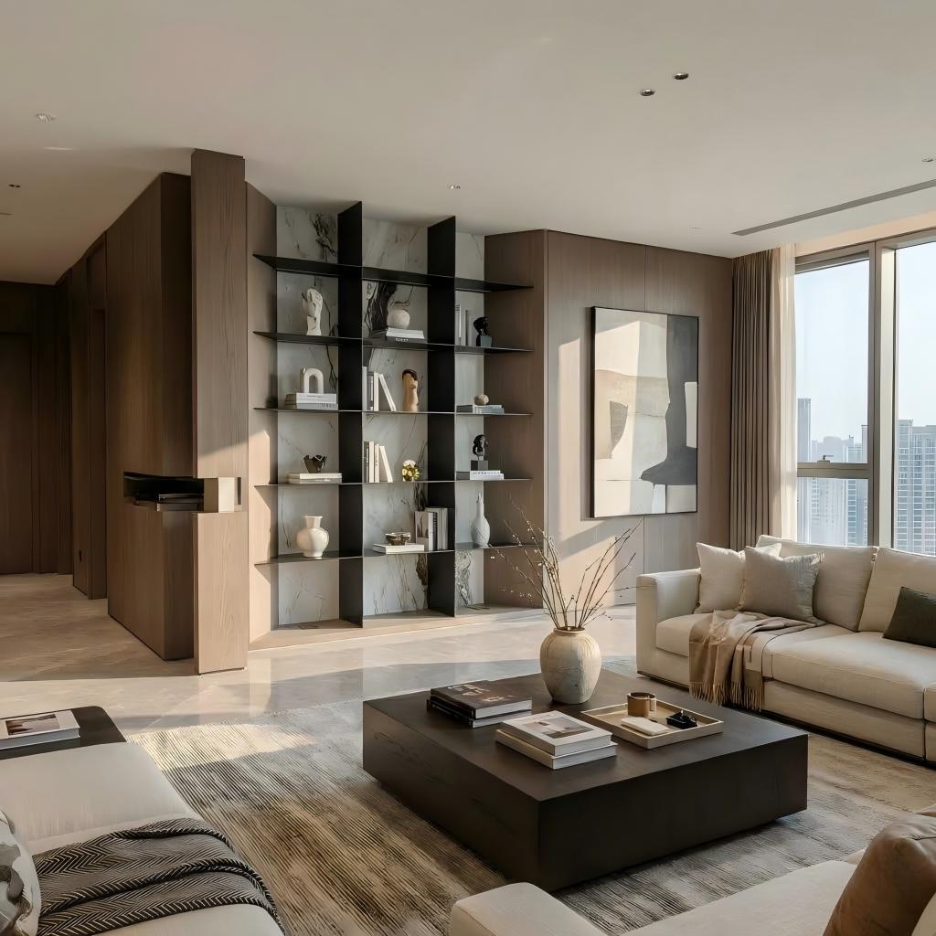
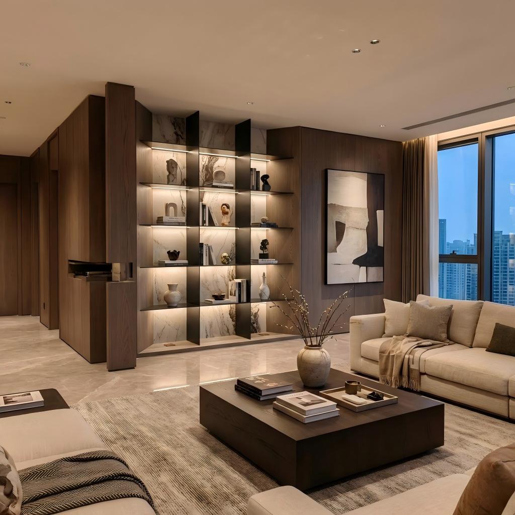
During the day, the shelving reads primarily through proportion and material contrast. At night, the integrated lighting creates a continuous horizontal rhythm and improves the visibility of displayed objects.
Final LED temperature, diffuser type, dimming, driver location, cable route and maintenance access should be confirmed before production. Reflection from marble, glass and dark anodized surfaces should also be reviewed through samples.
The system becomes more useful when each part of the elevation has a defined function rather than repeating identical shelves across the entire wall.
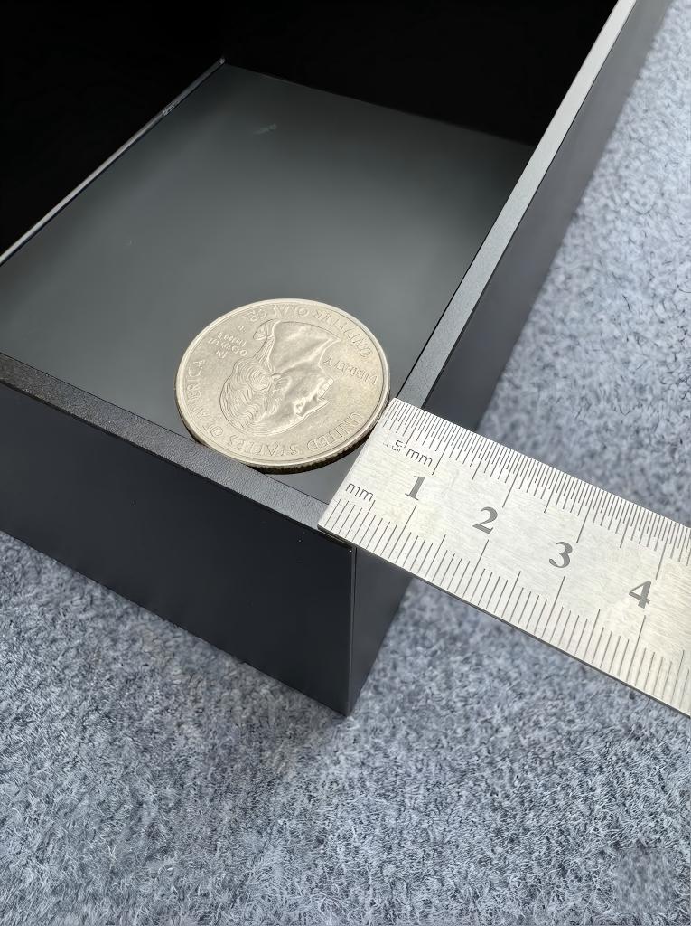
The existing page repeatedly describes a 5 mm aluminum shelf, but that description can mean different things: the visible front edge, plate thickness, profile wall, lighting slot or another measured component.
Before publishing 5 mm as a fixed technical specification, the production drawing should identify exactly what is being measured and how the complete shelf is supported.
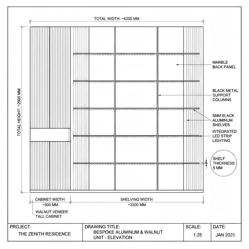
CAD and 3D files can help architects position the shelves within a larger interior elevation, but a presentation drawing is not automatically a production drawing.
The final approved shop drawing should identify shelf lengths and depths, wall fixing locations, back-panel joints, lower cabinet dimensions, LED channels, cable routes, driver access and installation sequence.
The proportions, support system and storage modules can be adjusted according to the room and intended use.
Combine display shelving, stone panels, lighting and lower storage around a focal wall.
Plan books, awards, art objects and concealed document storage in one coordinated elevation.
Use illuminated shelves for bottles and glassware with closed storage below.
Create a visually light product display while coordinating wiring and object loads.
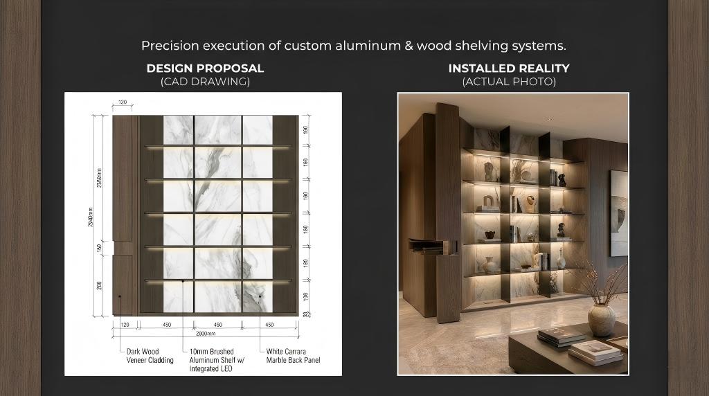
The existing comparison image can communicate the intended style, but a successful project also requires verified wall information, support details, electrical coordination and an installation sequence.
Real factory mock-up, shelf-load testing, lighting tests and completed installation photographs should be added when available. These materials would provide stronger evidence than additional lifestyle renderings.
Send wall dimensions, construction type, photographs, sockets and adjacent finishes.
List shelf contents, object sizes, approximate weights and required shelf spans.
Coordinate shelves, stone panels, lower cabinets, lighting and architectural joints.
Confirm support, aluminum section, finish, wiring, drivers and installation sequence.
Complete fabrication, alignment checks, lighting tests, surface inspection and export packing.
Customize shelf quantity, length, depth, spacing and relationship with lower cabinets.
Select project-approved anodized, powder-coated or other available surface treatments.
Coordinate walnut tone, stone or marble-look panels and concealed-storage fronts.
Plan LED temperature, diffuser, dimming, switching, drivers and cable access.
The wall substrate and intended display loads are as important as the visual dimensions. Providing both allows the shelf configuration to be evaluated more responsibly.
The current project description does not define this clearly. The final drawing should state whether 5 mm refers to the visible edge, plate thickness, profile dimension or another component.
Capacity depends on shelf length, depth, internal structure, fixing method, wall condition and load distribution. It should be confirmed for the approved configuration.
Yes. Shelf positions and dimensions can be developed according to the wall elevation, displayed objects and technical limitations.
Dimming, switching and sensor options can be discussed, subject to the selected LED, driver and electrical arrangement.
Potentially, but suitable reinforcement and fixing details must be designed according to the actual wall construction and shelf loads.
Send wall dimensions, wall type, photos, shelf layout, displayed-object weights, preferred finishes, electrical information and delivery destination.
Send the wall dimensions, construction type, shelf layout, displayed-object weights, preferred finishes and delivery location. ESM can use this information to discuss a project-specific solution.

 EN
EN